Industrial Design Steps for a Control Arm in Early-Stage Development
- Share
- Issue Time
- Dec 1,2025
The term "Industrial Design" here encompasses the entire process of taking a control arm from a concept to a production-ready design. It involves rigorous engineering analysis and validation.
1. System Definition and Packaging
This is the foundational step where the control arm's role and spatial constraints are defined.
Kinematic & Compliance (K&C) Requirements: The primary job of the control arm is to hold the wheel in a specific geometry as it moves. Engineers define precise targets for parameters like camber change, toe change, and roll center height throughout the suspension's travel.
Packaging Constraints: The control arm must fit within a very crowded space. Using 3D CAD packaging models, engineers ensure it clears components like the tire (at full lock and compression), brake calipers, driveshafts, the chassis frame, and the bodywork. Minimal clearance for snow/ice buildup is also considered.
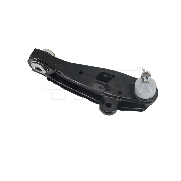
Attachment Point Definition: The locations of the inner bushings (which connect to the subframe/chassis) and the outer ball joint (which connects to the steering knuckle) are established based on the suspension hardpoints from the K&C analysis.
2. Conceptual Design and Architecture Selection
In this phase, the basic form and structure of the control arm are decided.
Type Selection: Engineers choose the best type for the application:
A-Arm / Wishbone (Upper & Lower): Common in double-wishbone suspensions.
Trailing Arm / Multi-Link: A more complex setup with multiple separate links for finer control.
Topology Exploration: Initial sketches and 3D models are created. Key decisions are made about the arm's basic shape, the number of mounting points, and whether it will be a single, solid piece or an assembly.
3. Detailed Engineering and Analysis (The Core Loop)
This is where the conceptual design is engineered into a robust, functional component.
Load Case Definition: Engineers identify all the extreme forces the control arm must withstand, such as:
Vertical Loads: Hitting a pothole or curb.
Braking & Acceleration Loads: Forces transferred from the wheel.
Cornering Forces: High-g turns.
Material Selection: The choice is critical for strength, weight, and cost.
Common Choices: Forged steel (high strength, cost-effective), Aluminum castings or forgings (lighter weight), or pressed steel (stamped and welded, often for cost-sensitive applications).
Finite Element Analysis (FEA): This is the most critical analysis tool.
Static Stress Analysis: Virtual loads are applied to the CAD model to identify high-stress areas and ensure the part does not yield (permanently deform).
Fatigue (Durability) Analysis: Simulates millions of load cycles to predict the component's lifespan and ensure it meets durability targets (e.g., 10 years or 150,000 miles).
Stiffness Analysis: Ensures the arm itself does not flex too much, as this would compromise suspension precision.
Weight Optimization: Using FEA results, material is strategically removed from low-stress areas (a process often called "topology optimization") to make the component as light as possible without sacrificing strength. This is crucial for vehicle performance and fuel efficiency.
4. Design for Manufacturing (DFM) and Assembly (DFA)
The design is refined for efficient and cost-effective production.
Manufacturing Process Finalization: The chosen material and design dictate the process:
Forging: Excellent strength-to-weight ratio; common for high-performance arms.
Casting: Allows for complex shapes; common for aluminum arms.
Stamping & Welding: Cost-effective for high-volume steel arms.
DFM/A Review: The design is reviewed to ensure it can be easily:
Made: Avoiding features that are difficult to forge, cast, or machine.
Assembled: Ensuring there is enough space for tools to install bolts and that the arm can be fitted to the vehicle easily on the assembly line.
5. Component Integration and Joint Design
The control arm doesn't work in isolation; its connection points are designed.
Bushing Design: The inner bushings are designed to provide specific compliance. Their stiffness in different directions affects both ride comfort (isolating vibrations) and handling sharpness.
Ball Joint Design: The outer ball joint is specified or designed to handle the required load, angular range of motion, and lifespan.
6. Prototyping and Validation
Virtual models are validated with physical parts.
Rapid Prototyping: 3D-printed plastic or CNC-machined aluminum parts may be used for initial fit-checks in a physical vehicle.
"Mule" Vehicle Testing: The first functional prototypes (made from the intended production material and process) are installed in test vehicles. Engineers evaluate real-world handling, noise, and durability.
Lab Durability Testing: Prototype arms are mounted to rigs and subjected to accelerated fatigue tests that simulate a lifetime of abuse in a matter of weeks.
7. Design Finalization and Release
Design Iteration: The FEA models are correlated with physical test data. If any failures occur, the design is modified, and the analysis-validation loop is repeated.
Production Release: Once the design meets all performance, durability, and cost targets, the final CAD data, drawings, and specifications are released to the manufacturing team to begin production tooling.